
Ambiguous Cylinder Illusion

How the ambiguous object works

In arts and entertainment, optical illusions have been used to create the impression of impossibility. In 2016, Professor Kokichi Sugihara in Japan found ambiguous cylinders that appear drastically different when viewed from two specific viewpoints. Suppose we have two viewers looking down on a curve floating above the \(xy-\)plane. The first viewer is a person looking at the curve, and the second viewer is in the mirror. We would like the two viewers to look down on the curve at 45-degree angles on opposite sides of the \(xy-\)plane. From the viewers’ perspectives, it looks as if they are viewing the curves and respectively, as shown in the following picture.
(https://m-repo.lib.meiji.ac.jp/dspace/bitstream/10291/19877/1/jma_12_1_2.pdf)

The key to the ambiguous cylinder is that the top of the cylinder is not a planar curve. This can be explained by the natural assumption of human visual perception. Natural assumption regard in visual depth three-dimensional object has width, height, and depth. As we know, two-dimensional figures don't have information on depth. But humans have the capacity to perceive a two-dimensional figure as a three-dimensional object. That's because our natural assumptions subconsciously add information on depth. When we see an illustration of an "impossible" object, we subconsciously try to perceive the object based on our natural assumptions.

Our design of an ambiguous cylinder

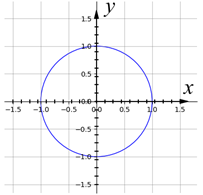
Our design consists of a curve of two diamonds and a curve of a circle. The curve of two diamonds is defined as following:
Upper part: \[y=\left\{\begin{split} \begin{aligned} &1+x, &-1 &\le x \lt -0.5 \\ &-x, &-0.5 &\le x \lt 0\\ &x, &0 &\le x \lt 0.5 \\ &1-x, &0.5 &\le x \le 1\\ \end{aligned} \end{split}\right.\] Lower part: \[y=\left\{\begin{split} \begin{aligned} &-1-x, &-1 &\le x \lt -0.5 \\ &x, &-0.5 &\le x \lt 0\\ &-x, &0 &\le x \lt 0.5 \\ &-1+x, &0.5 &\le x \le 1\\ \end{aligned} \end{split}\right.\]
The curve of a unit circle is defined as following: \[x^2+y^2=1\]
We design a cylinder with OpenSCAD to show these two different curves. From the viewers’ perspectives, it looks as if they are viewing two curves respectively. The design looks like a vertical cylinder, but its section appears to be different; in one view it appears to be two diamonds, while in the other view it appears to a circle.

Why to use this design

  1. The two curves in this design are different enough to show the ambiguous cylinder illusion. Our design looks like a circular cylinder from the front and a two-diamond cylinder in the mirror. It is a magic phenomenon. The direct views of the objects and their mirror images generate quite different interpretations of the 3D shapes. We cannot correct our interpretations although we logically know that they come from the same objects. Even if the object is rotated in front of a viewer, it is difficult to understand the true shape of the object, and thus the illusion does not disappear.
  2. The unusual visual effects of ambiguous cylinder illusion might be useful. At least upon one's first encounter with ambiguous cylinders, they are surprising and mysterious. Optical illusions including ambiguous cylinders are potential resources for new products in many fields such as education, architecture, art, entertainment, advertising, and tourism. In the above design, we investigate the magic phenomenon of ambiguous cylinder illusion. This helps us to better understand the process of human visual perception.
In the above design, we investigate the magic phenomenon of ambiguous cylinder illusion. This helps us to better understand the process of human visual perception.

Comments

Popular posts from this blog

Do Over: Integration Over a Region in a Plane

Throughout the semester we have covered a variety of topics and how their mathematical orientation applies to real world scenarios. One topic we discussed, and I would like to revisit, is integration over a region in a plane which involves calculating a double integral. Integrating functions of two variables allows us to calculate the volume under the function in a 3D space. You can see a more in depth description and my previous example in my blog post, https://ukyma391.blogspot.com/2021/09/integration-for-over-regions-in-plane_27.html . I want to revisit this topic because in my previous attempt my volume calculations were incorrect, and my print lacked structural stability. I believed this print and calculation was the topic I could most improve on and wanted to give it another chance. What needed Improvement? The function used previously was f(x) = cos(xy) bounded on [-3,3] x [-1,3]. After solving for the estimated and actual volume, it was difficult to represent in a print...

Minimal Surfaces

Minimum surfaces can be described in many equivalent ways. Today, we are going to focus on minimum surfaces by defining it using curvature. A surface is a minimum surface if and only if the mean curvature at every point is zero. This means that every point on the surface is a saddle point with equal and opposite curvature allowing the smallest surface area possible to form. Curvature helps define a minimal surface by looking at the normal vector. For a surface in R 3 , there is a tangent plane at each point. At each point in the surface, there is a normal vector perpendicular to the tangent plane. Then, we can intersect any plane that contains the normal vector with the surface to get a curve. Therefore, the mean curvature of a surface is defined by the following equation. Where theta is an angle from a starting plane that contains the normal vector. For this week’s project, we will be demonstrating minimum surfaces with a frame and soap bubbles! How It Works Minimum surfac...

Do Over: Ruled Surfaces

Why to choose this project to repeat For the do over project, I would like to choose the ruled surfaces. I don't think my last project was creative, and the 3D printed effect was not very satisfactory. In the previous attempts, all the lines are connected between a straight line and a circle. This connection structure is relatively uncomplicated. The printed model has too many lines, resulting in too dense line arrangement. The gaps between lines are too small, and the final effect is that all the lines are connected into a curved surface, which is far from the effect I expected. What to be improved In this do over project, I would like to improve in two aspects. Firstly, a different ruled surface is chosen. In the previous model, one curve is a unit circle on the \(x-y\) plane, and the ruled surface is a right circular conoid. In this do over project, it is replaced by two border lines. Each borderline is in the shape of an isosceles right triangl...